
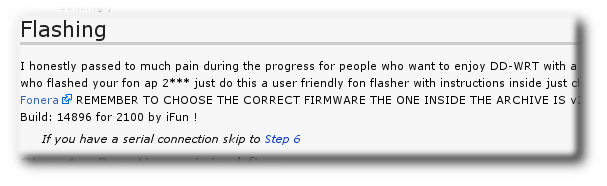
In my previous post I’ve described how to access the serial port of a Fonera 2100 by using a Raspberry Pi with minicom. Being able to access the serial port makes it very easy to flash DD-WRT on the Fonera because according to these instructions we can skip to Step 6.
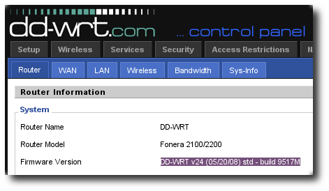
Following these instructions I’ve flashed my Fonera with DD-WRT v24 (05/20/08) std - build 9517M.
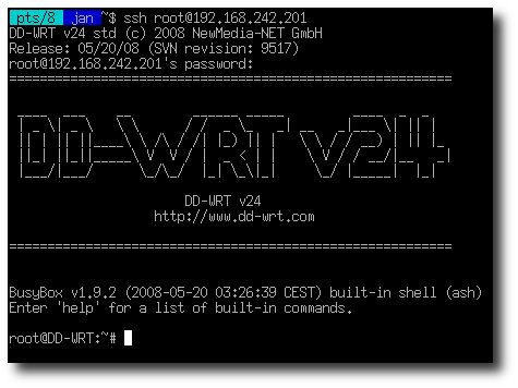
Then, I have put my DD-WRT-Fonera in Client Bridge mode following these instructions. I’ve also enabled SSH, so I can login over the network.
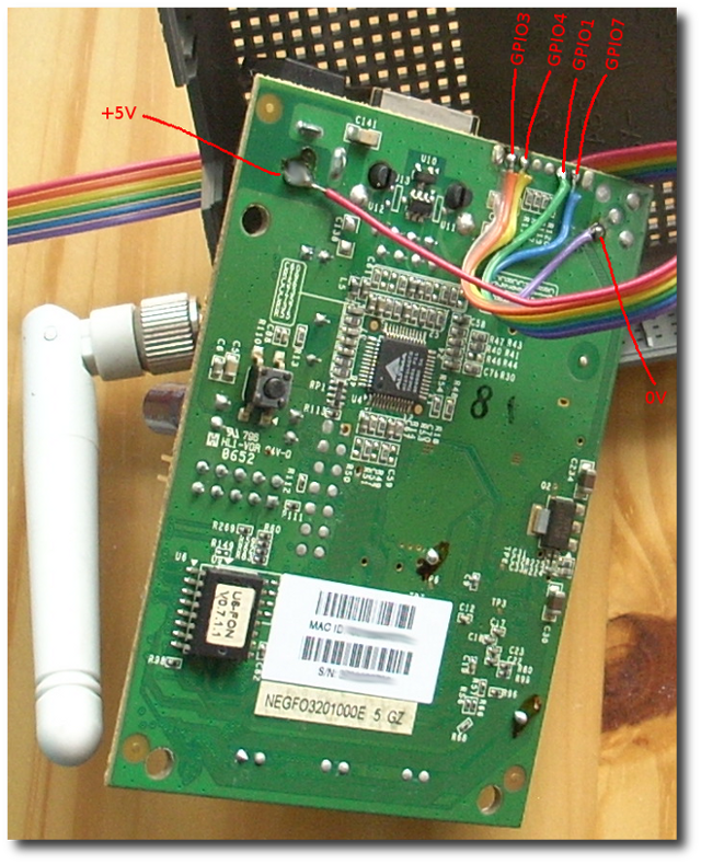
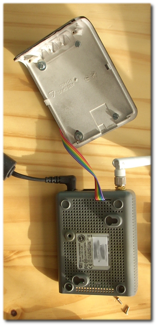
The interesting part is that the fonera has some free GPIO pins, that can be controlled by software. For example:
set GPIO3 to output : echo 1 > /proc/gpio/3_dir
GPIO3 = on (3.3V)   : echo 1 > /proc/gpio/3_out
GPIO3 = off         : echo 0 > /proc/gpio/3_out

set GPIO4 to output : echo 1 > /proc/gpio/4_dir
GPIO3 = on (3.3V)   : echo 1 > /proc/gpio/4_out
GPIO3 = off         : echo 0 > /proc/gpio/4_out

set GPIO1 to output : echo 1 > /proc/gpio/1_dir
GPIO3 = on (3.3V)   : echo 1 > /proc/gpio/1_out
GPIO3 = off         : echo 0 > /proc/gpio/1_out

set GPIO7 to output : echo 1 > /proc/gpio/7_dir
GPIO3 = on (3.3V)   : echo 1 > /proc/gpio/7_out
GPIO3 = off         : echo 0 > /proc/gpio/7_out
To finish this story, I’ve ordered a 4-Channel Relay board at dx.com and connected it to the Fonera.
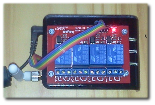
Although the voltage output of the Fonera GPIO’s is 3.3V this works very well.