January 2010 Archives
Sat Jan 30 11:55:37 CET 2010
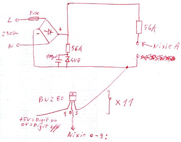
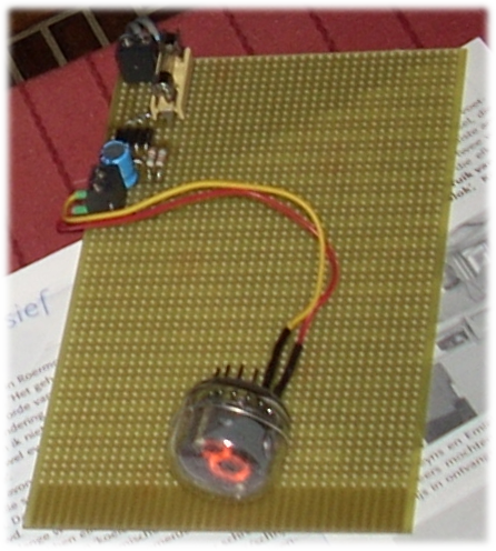
Switch Nixie digits off/on with 0V/+5V
Switching off/on a digit of a nixie tube is normally done by using a 7441/74141 NIXIE Tube Driver or a transistor like the MPSA42.
I don't have those parts lying around here, and it's snowing outside, so I'm not in the mood to go shopping
But I do have some BUZ80 SIPMOS Power Transistor lying around. They are a littlebit oversized, but wil do the job. Anyway, a MPSA42 with resistor will probably be a cheaper and therefore a better solution.
This is the result with 11 BUZ80's
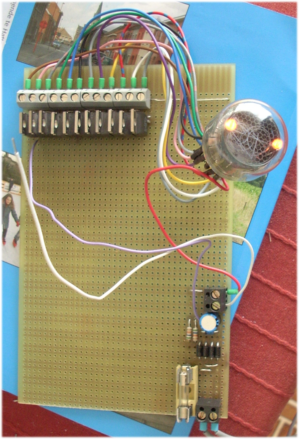
Next step is to add a PIC to the circuit.
To be continiued
I don't have those parts lying around here, and it's snowing outside, so I'm not in the mood to go shopping
But I do have some BUZ80 SIPMOS Power Transistor lying around. They are a littlebit oversized, but wil do the job. Anyway, a MPSA42 with resistor will probably be a cheaper and therefore a better solution.
This is the result with 11 BUZ80's
Next step is to add a PIC to the circuit.
To be continiued
Thu Jan 28 22:53:34 CET 2010
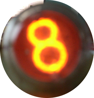
Power a Nixie tube
Through the years, I have collected a lot of 'junk', like for example a nixie tube and thought it would be interesting to do something with it.

After reading this Build a Nixie Tube Digital Clock-Web Page and taking a look at the circuit schematic I have decided to take the same approach to power the nixie tube.
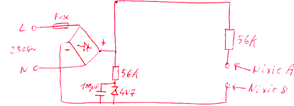
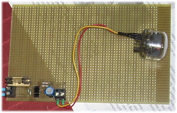
And yes, it works
The next step will be to add a circuit that can switch the digits 0-9 on and off by using 0V - 5V, so a PIC can be used to drive the digits.
To be continiued
After reading this Build a Nixie Tube Digital Clock-Web Page and taking a look at the circuit schematic I have decided to take the same approach to power the nixie tube.
And yes, it works
The next step will be to add a circuit that can switch the digits 0-9 on and off by using 0V - 5V, so a PIC can be used to drive the digits.
To be continiued